| 1 |
Maximum allowable distance between the antennas |
16 m |
| 2 |
Ambient temperature in the place of RC and TR units installation (allowable temperature of RC and TR units housing during operation) |
-45…+85 °С |
| 3 |
The maximum allowable temperature of the antennas external (radiating) end (during executing section 3.2):
- version V2.1
- version V2.2 with PTFE plug
- version V2.2 with ceramic plug * note 1
- version V2.3 |
+150 °С
+220 °С
+400 °С
+200 °С |
| * Note 1. At the customer’s request antennas can include high temperature ceramics with working temperature of up to 800°C, which allow insertion of antenna directly into the kilns flame area. |
| 4 |
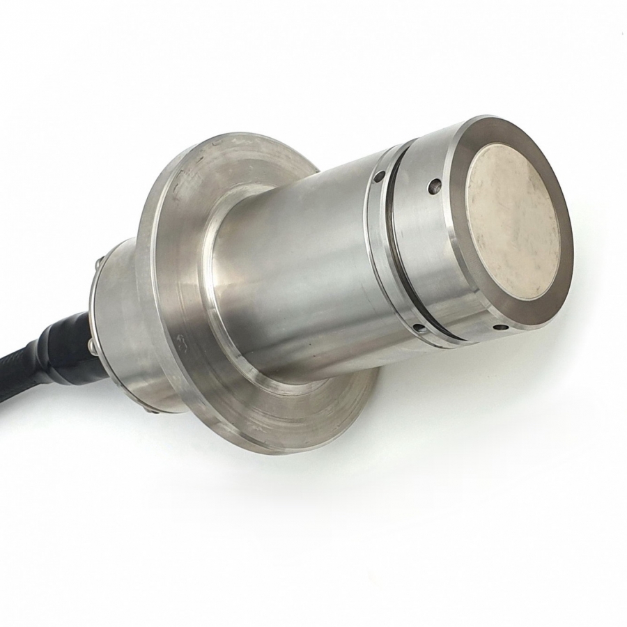
Size of holes in the tank walls:
- for antennas made of rectangular waveguide, not less than
- for antennas made of stainless steel pipe |
12×25 mm
Ø 35 mm |
| 5 |
Operating wavelength range of probing microwave signal |
3 cm |
| 6 |
Average power of the probing signal, not more than |
3 µW |
| 7 |
Maximum power flux density of microwave signal radiated by the transmitter and its antenna at a distance of 0.5 m (averaged value for the period), not more than |
0,5 µW/cm2 |
| 8 |
Output stage is made using p-type field transistor |
|
| 9 |
Output voltage:
- when tank is not filled at a controlled level (microwave signal passes through the tank without weakening), not less than
- when tank is filled at a controlled level, not more than |
+UBsup -1 V
1V |
| 10 |
Electric load on receiver output (maximum allowable load current) |
150 mА |
| 11 |
Alarm supply voltage (Usup) (DC power supply):
- nominal
- maximum allowable
- minimum allowable |
+24 V
+27 V
+20 V |
| DNR18US24 "XPPOWER" type supply unit can be used as a power supply |
| 12 |
Current consumed by alarm in supply network (excluding the current consumed by the external load), not more than |
100 mА |
| 13 |
Galvanic isolation of electrical circuits of alarm electronic units from the housing, not less than |
500 V |
| 14 |
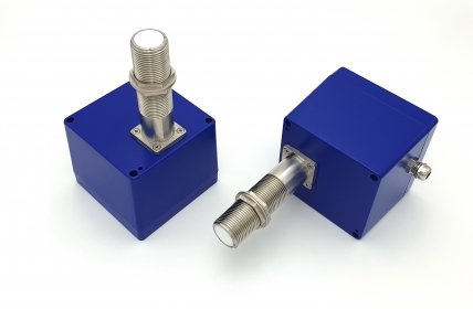
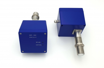
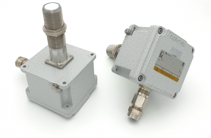
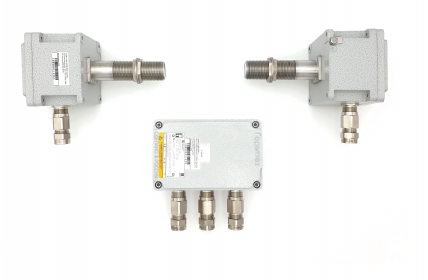
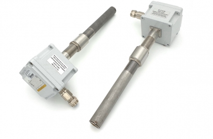
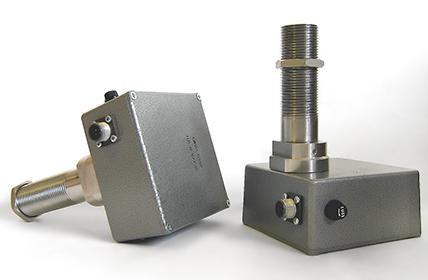
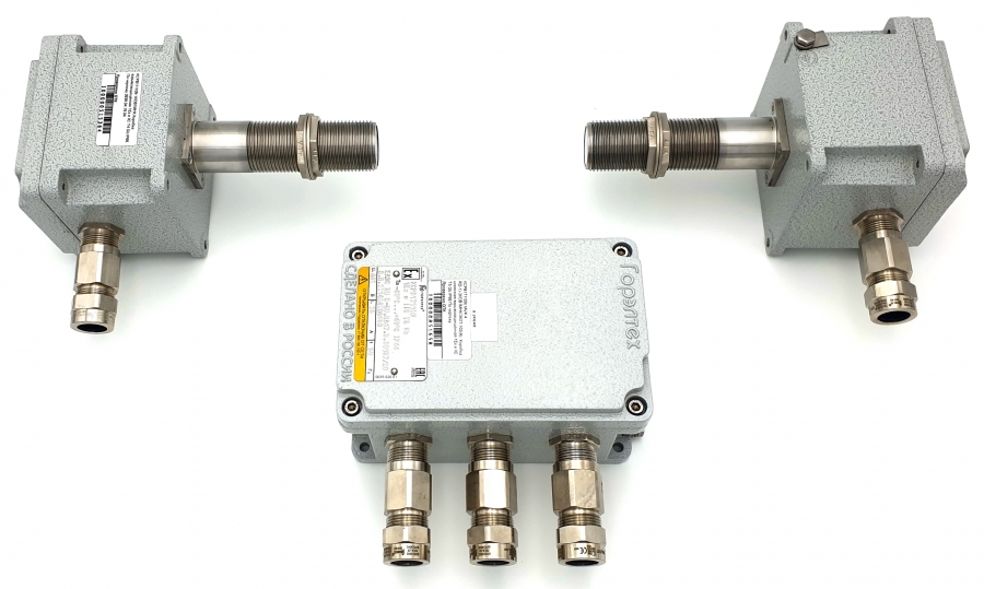
Overall dimensions of receiving and transmitting units (without antenna):
- version SIUR-03V2.1
- version SIUR-03V2.2/3 |
140×140×85 mm
135×130×100 mm |
| 15 |
Overall dimensions of waveguide antennas:
- version SIUR-03V2.1
- version SIUR-03V2.1
- version SIUR-03V2.2
- version SIUR-03V2.3 (4) |
(f)46×46mm,L=120...300mm
(s)33×25mm,L=120...300mm*
Ø33mm, L=200...1500mm *
Ø33 mm, L=120 mm |
| * Note 2. Antenna length is determined by the conditions of use and is specified during ordering. |
| 16 |
Length of supplied cables for electronic units with cable connectors (cable is not supplied with units equipped with sealed lead-ins) |
5 m |
| 17 |
Dust and moisture ingress protection rating of alarm electronic units according to IEC 60529 |
IP65 |
| 18 |
Unit weights:
- transmitter TR
- receiver RC |
1,2 kg
1,2 kg |
| 19 |
Warranty period |
24 months |